Torsional Stress Formula in Design of Power Transmission Systems
Ever wondered how the axles in your car withstand the immense twisting forces as you accelerate? Or how massive turbine shafts in power plants manage to spin continuously under incredible load? The answer lies in understanding torsional stress and, crucially, the torsional stress formula. For engineers, students, and anyone involved in mechanical design, mastering this formula is essential for creating safe, efficient, and reliable power transmission systems.
Understanding Torsional Stress
Torsional stress is the stress induced in a material when it is subjected to a twisting force, or torque. Imagine twisting a metal rod – the internal resistance of the material to this twisting is what we call torsional stress. This stress is critical in designing shafts, axles, and any component that transmits rotational power.
Unlike tensile and compressive stress, which act perpendicularly to the surface, torsional stress acts parallel to the surface. It's a shear stress, meaning it represents the force acting tangentially on a cross-section of the material. Think of it like trying to slide one layer of the material past another.
The Torsional Stress Formula: Unveiled
The torsional stress formula allows us to calculate the maximum shear stress within a shaft subjected to torque. It's a cornerstone of mechanical engineering and structural design. The formula is:
τ = (T r) / J
Where:
- τ (tau) = Torsional shear stress (usually in Pascals or psi)
- T = Applied torque (usually in Newton-meters or lb-in)
- r = Radius of the shaft (usually in meters or inches)
- J = Polar moment of inertia (usually in meters4 or inches4)
Let's break down each component of this formula to fully grasp its meaning and application.
Defining Torque (T)
Torque is the twisting force applied to the shaft. It’s the rotational equivalent of linear force. In power transmission systems, torque is typically generated by an engine or motor and transmitted through shafts to perform work. The higher the torque, the greater the twisting force on the shaft.
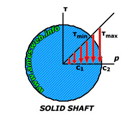
Understanding Radius (r)
The radius (r) is the distance from the center of the shaft to the point where the stress is being calculated. The maximum torsional stress always occurs at the outermost surface of the shaft (i.e., at the radius). This is because the material furthest from the center experiences the greatest strain during torsion.
The Role of Polar Moment of Inertia (J)
The polar moment of inertia (J) is a geometric property of the shaft's cross-section that represents its resistance to twisting. It depends on the shape and dimensions of the cross-section. For a solid circular shaft, the formula for J is:
J = (π d4) / 32 or J = (π r4) / 2
Where 'd' is the diameter and 'r' is the radius of the shaft. For a hollow circular shaft (a tube), the formula is:
J = (π (D4 - d4)) / 32
Where 'D' is the outer diameter and 'd' is the inner diameter. A higher polar moment of inertia indicates a greater resistance to torsional deformation.
Applying the Torsional Stress Formula: A Step-by-Step Example
Let's say we have a solid steel shaft with a diameter of 50 mm transmitting a torque of 500 Nm. We want to calculate the maximum torsional stress in the shaft.
Step 1: Calculate the radius (r).
r = d/2 = 50 mm / 2 = 25 mm = 0.025 m
Step 2: Calculate the polar moment of inertia (J).
J = (π d4) / 32 = (π (0.05 m)4) / 32 ≈
6.136 x 10⁻⁸ m4
Step 3: Apply the torsional stress formula.
τ = (T r) / J = (500 Nm 0.025 m) / (6.136 x 10⁻⁸ m4) ≈
20.37 x 10⁶ Pa =
20.37 MPa
Therefore, the maximum torsional stress in the shaft is approximately 20.37 MPa.
Practical Applications and Considerations
The torsional stress formula is not just a theoretical concept; it's a crucial tool in real-world engineering applications. Here are a few:
Shaft Design: Engineers use the formula to determine the appropriate diameter of shafts for transmitting power, ensuring they can withstand the applied torque without failing. Material Selection: The formula helps in selecting materials with sufficient shear strength to resist torsional stresses. Failure Analysis: If a shaft fails due to torsion, the formula can be used to analyze the stress levels and identify the cause of failure. Optimizing Design: By understanding the relationship between torque, radius, and polar moment of inertia, engineers can optimize designs to minimize material usage and weight while maintaining structural integrity.
When using the torsional stress formula, remember that it assumes the material is linearly elastic and that the shaft is perfectly circular. For more complex geometries or materials, more advanced analysis techniques, such as finite element analysis (FEA), might be necessary.
Advantages and Limitations of the Formula
Advantages:
- Simple and easy to use for basic shaft designs.
- Provides a good estimate of maximum torsional stress.
- Helps in preliminary design and material selection.
Limitations:
- Assumes linear elasticity and a circular cross-section.
- Does not account for stress concentrations (e.g., at sharp corners or keyways).
- May not be accurate for complex geometries or non-uniform loading.
Case Study: Automotive Axle Design
Consider the design of an automotive axle. The axle transmits power from the differential to the wheels, experiencing significant torsional stress. Engineers use the torsional stress formula, combined with safety factors, to determine the required diameter and material properties of the axle. They also consider factors like fatigue life and stress concentrations at the wheel mounting points.
Advanced simulation tools are often used to validate the design and ensure the axle can withstand the expected operating conditions, including sudden acceleration and braking.
Torsional Stress vs. Tensile and Compressive Stress
While all types of stress contribute to the overall state of a material under load, torsional stress is distinct from tensile and compressive stress. Tensile stress occurs when a material is pulled, while compressive stress occurs when a material is pushed. Both act perpendicular to the surface. Torsional stress, as we've discussed, is a shear stress, acting parallel to the surface due to twisting forces.
Understanding the differences between these stress types is crucial for comprehensive structural analysis. In many real-world scenarios, components experience a combination of all three, requiring a more complex analysis.
Frequently Asked Questions
What is the unit of measurement for torsional stress?
The unit of measurement for torsional stress is typically Pascals (Pa) or pounds per square inch (psi). These are units of pressure, representing force per unit area.
How does the material of the shaft affect torsional stress?
The material's shear modulus (a measure of its stiffness in response to shear stress) and its yield strength are crucial. A material with a higher shear modulus will deform less under the same torque, while a higher yield strength means it can withstand higher stresses before permanent deformation occurs. The torsional stress formula itself doesn't directly include material properties, but those properties are used to determine if the calculated stress is acceptable.
What are some common causes of torsional stress failures?
Common causes include exceeding the material's yield strength, fatigue due to cyclic loading, stress concentrations at geometric discontinuities (e.g., keyways, holes), and manufacturing defects. Corrosion can also weaken a material, making it more susceptible to torsional failure.
How can I reduce torsional stress in a shaft?
You can reduce torsional stress by increasing the shaft's diameter (which increases the polar moment of inertia), using a material with a higher shear modulus or yield strength, reducing the applied torque, or eliminating stress concentrations through smoother transitions and careful design of features like keyways.
Is torsional stress the same as torque?
No, torsional stress is the internal stress within a material caused by the applied torque. Torque is the twisting force itself, while torsional stress is the material's response to that force. They are related by the torsional stress formula, but they are distinct concepts.
What is the safety factor in torsional stress calculations?
A safety factor is a multiplier applied to the calculated stress to ensure that the component can withstand loads beyond the expected operating conditions. It accounts for uncertainties in material properties, loading conditions, and manufacturing tolerances. A higher safety factor results in a more conservative design.
Conclusion
The torsional stress formula is a fundamental tool for anyone involved in the design and analysis of power transmission systems. By understanding the relationships between torque, radius, polar moment of inertia, and material properties, engineers can create robust and reliable components that can withstand the twisting forces they'll encounter in service. Mastering this formula is a key step in ensuring the safe and efficient operation of countless machines and systems that power our world. So, keep practicing, keep exploring, and keep designing!
Posting Komentar untuk "Torsional Stress Formula in Design of Power Transmission Systems"